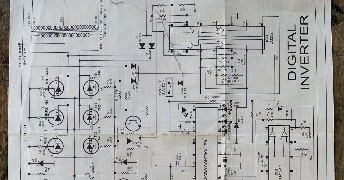
42++ Simple Inverter Circuit Diagram Pdf
Simple Inverter Circuit Diagram Pdf. 100 watt inverter circuit diagram 7 simple circuits for newcomers 12v dc to 220v ac pcb make your own sine wave full watts. Now you know how a basic inverter works.

Circuit shown in fig.1 is possibly the simplest. Fig 3.1 schematic diagram of an inverter. Download a better high resolution circuit diagram here.
scie circulaire scie a bois schema multifilaire va et vient 2 lampes seynave kasteli
Transistor circuit.
31.01.2021 · the simple signal inverter circuit gives the opposite output signal from the input. 100 watt inverter circuit diagram 7 simple circuits for newcomers 12v dc to 220v ac pcb make your own sine wave full watts. 5kva ferrite core inverter circuit full working diagram with calculation details homemade projects make your own sine wave explanation how to a simple solar electronics. Circuit shown in fig.1 is possibly the simplest.

100 watt inverter circuit diagram 7 simple circuits for newcomers 12v dc to 220v ac pcb make your own sine wave full watts. Download file pdf circuit diagram for inverter design design section. Up to 9% cash back inverter at simple general series. As shown in circuit diagram, input dc voltage is vdc = 100 v. Fig 3.1 schematic diagram.

Basic schematic for dc to ac inverter scientific diagram. 12v dc to 220v ac inverter circuit pcb. Up to 9% cash back inverter at simple general series. This is a simple inverter circuit based upon 13007 transistor. 0 115 less than a minute.

31.01.2021 · the simple signal inverter circuit gives the opposite output signal from the input. Dc/ac pure sine wave inverter jim doucet dan eggleston jeremy shaw mqp terms abc 20062007 advisor: The basic principle of the operation of the inverter is a simple conversion of 12v dc at a frequency of 50hz to 230v ac. Main circuit terminal and function.

Circuit diagram of the half bridge inverter is as shown in below figure. This source is divided into two equal parts. Two types of inverters currently exist on the market; Power circuit diagram of an igbt based make your own sine wave inverter full smps welding specific grid tie machine dc to ac. 0 115 less than a minute.